Skip to content
Paradigm 3D
Request a quote
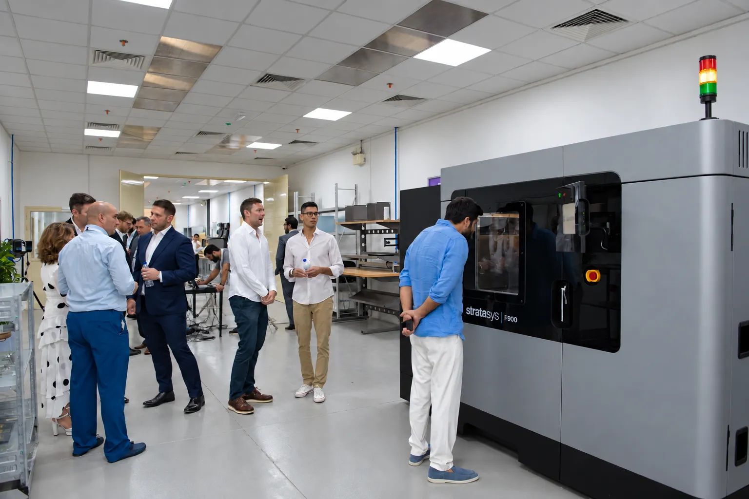
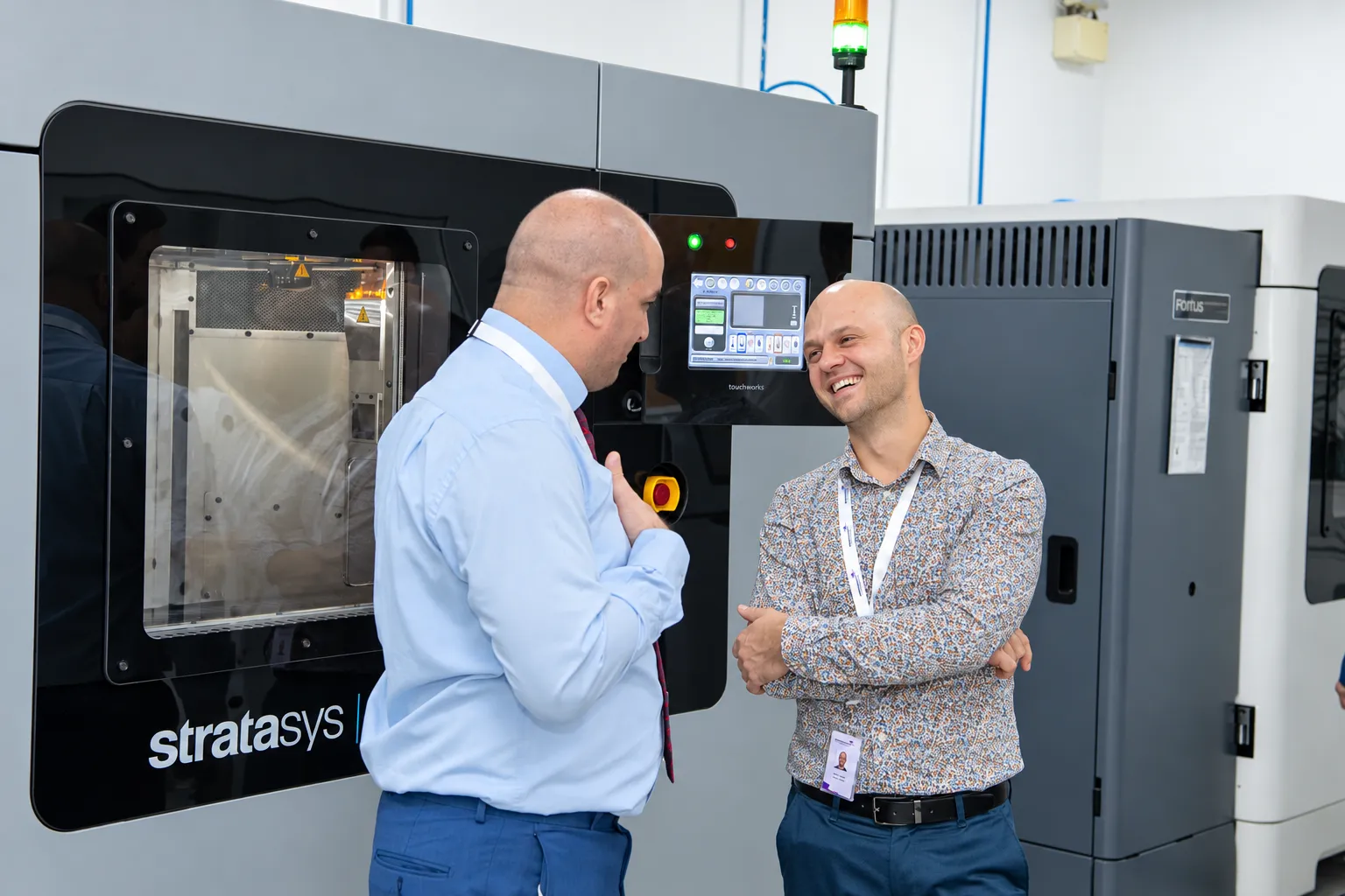
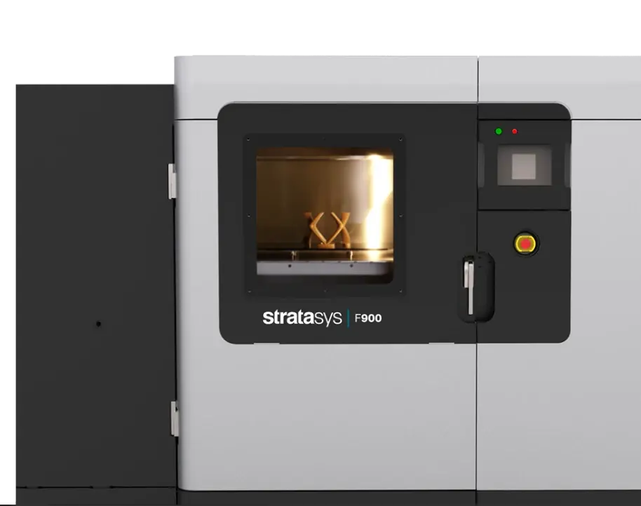
Stratasys F900 FDM production system at Paradigm 3D in Jebel Ali

FDM 3D printing.Built big and tough.

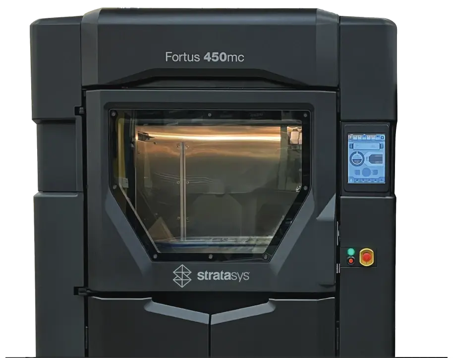
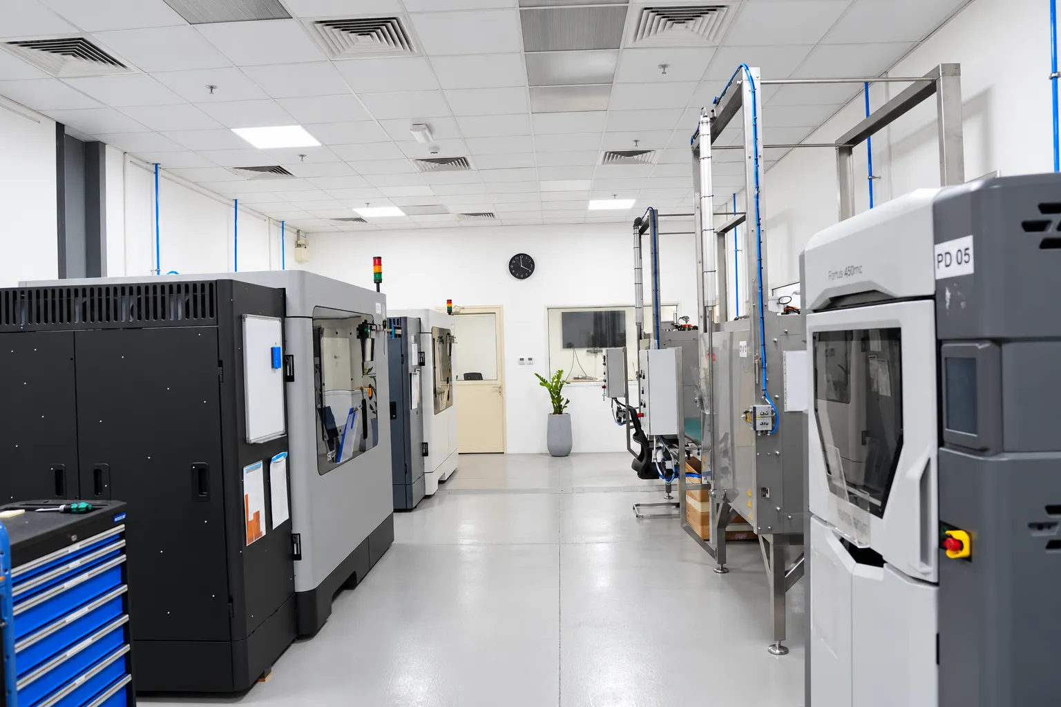
Industrial fused deposition modelling on Stratasys F900 and Fortus 450mc systems in Jebel Ali. Engineering thermoplastics, including ULTEM™ 9085, for parts up to 914 × 610 × 914 mm.

2 systemsStratasys F900 and Fortus 450mc
914 mmLargest build dimension
18Engineering thermoplastics
±0.089 mmF900 accuracy, manufacturer-stated
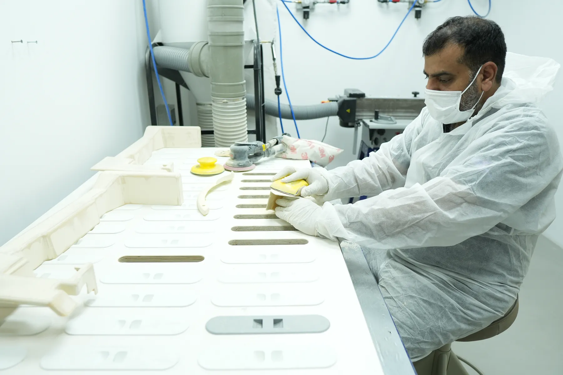
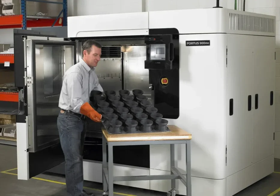
Operator unloading a batch of FDM parts from a Stratasys F900

Built from filament,one layer at a time.

A heated nozzle extrudes engineering thermoplastic along computed toolpaths inside a heated build chamber. Support material holds overhangs and is removed after the build.

Systems
Stratasys F900, Stratasys Fortus 450mc
Largest envelope
914 × 610 × 914 mm on the F900
Layer thickness
0.127–0.508 mm, material dependent (F900 manufacturer data)
Materials
18 thermoplastics, from ABS and ASA to ULTEM™ and PEKK
  1. Review and orient

    We check the CAD, orient the part for load direction and finish, and plan where support is needed.

  2. Extrude each layer

    The nozzle deposits model and support material along controlled toolpaths in a heated chamber.

  3. Remove supports

    Support material is removed and the part is cleaned, ready for finishing.

  4. Finish and inspect

    Sanding, paint or inserts as specified, then a check of critical dimensions and interfaces.

When FDM is right,and when it isn't.

We recommend the process that suits the part. Here is how FDM compares with our SLS and metal systems.

Choose FDM when

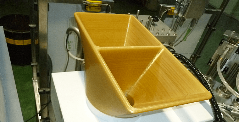
  • The part is large, up to 914 × 610 × 914 mm in one piece.
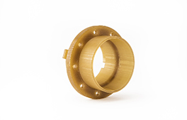
  • You need a specific engineering thermoplastic such as ULTEM™ 9085, PC, ASA or Nylon 12CF.
  • Quantities are low and moulds or tooling would never pay back.
  • Layer lines are acceptable, or the part will be sanded and painted.
Look at another process when

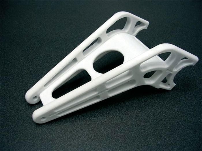
  • You need many small, intricate parts at once. SLS nests them in one build.
  • Internal channels cannot take support material. SLS parts are supported by the surrounding powder.
  • The part must be metal, or carry loads and temperatures beyond polymers. Consider metal LPBF.
  • Strength must be even in every direction. FDM parts are strongest along their layers.
Envelopes and layer ranges are manufacturer-stated machine specifications. Usable part size depends on orientation and build setup.
CompareFDMSLSMetal LPBF
Largest envelope914 × 610 × 914 mm (F900)340 × 340 × 600 mm (EOS P 396)300 × 300 × 450 mm (EP-M300)
Layer thickness0.127–0.508 mm0.06–0.18 mm20–120 μm
Materials18 engineering thermoplastics, including ULTEM™, PC, ASA and PEKK13 polyamide, flame-retardant, filled and flexible powders7 alloy families, from stainless steel to titanium and nickel
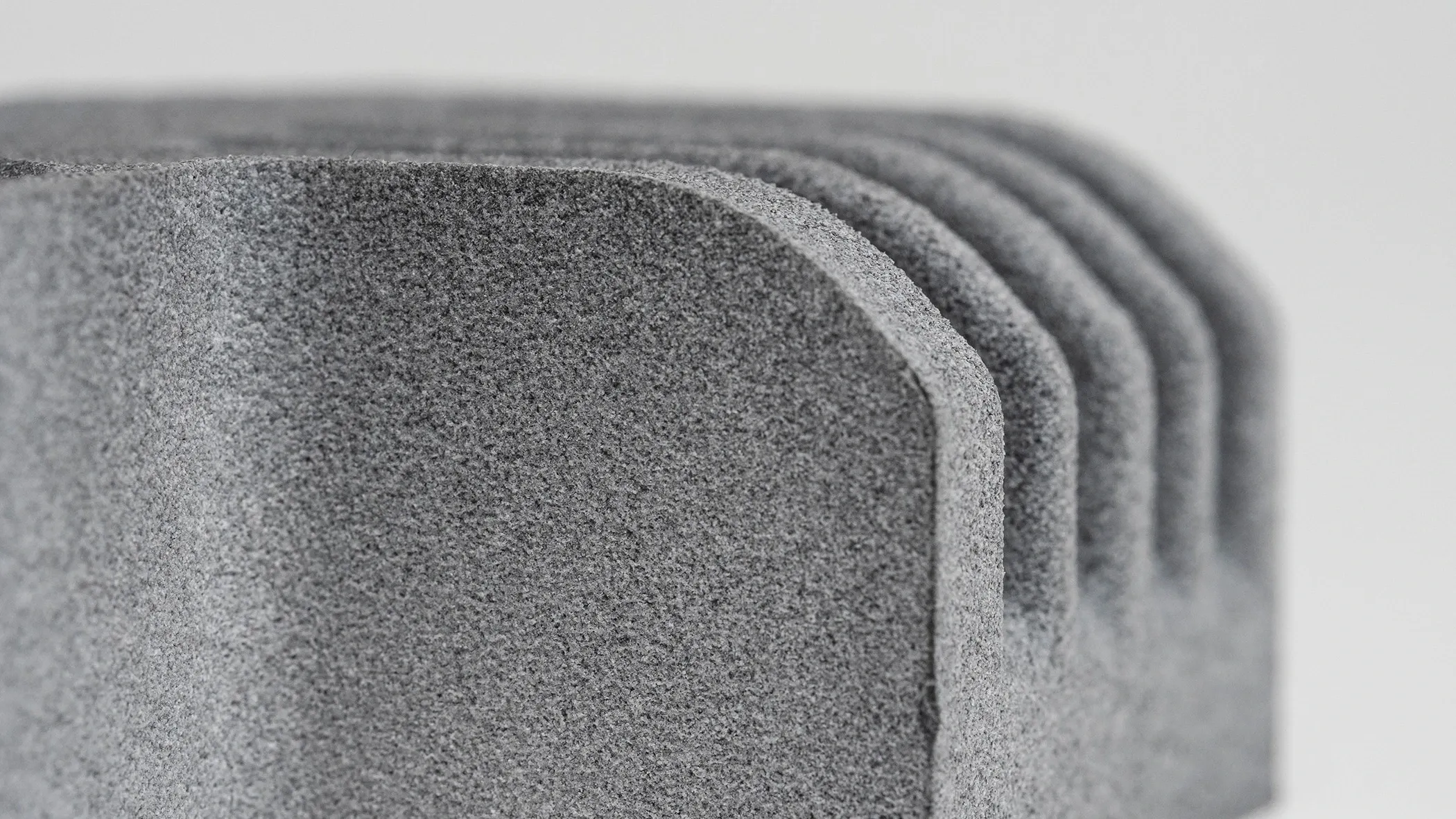
As-built surfaceVisible layer linesFine, matte textureTextured metal; critical faces often machined
SupportsSupport material under overhangsNone; the powder supports the partSupports and a build plate, removed after the build
StrengthTough thermoplastic parts, strongest along the layersTough nylon parts with complex geometryFully dense metal parts
Typical usesCabin interior parts, large housings, jigs and fixturesDucting, housings, clips and serial batchesValve internals, manifolds, impellers and brackets

Design notesthat save a rebuild.

Send the CAD as it is. These are the points our engineers check first, and where a small change makes a better FDM part.

Orientation and load

Parts are strongest along their layers. Tell us the load direction and we orient the build to suit it.

Overhangs and supports

Overhangs need support material. Leave access so it can be removed from pockets and internal features.

Walls and ribs

Thin walls and fine ribs depend on the material and toolpath. We review them against your geometry before quoting.

Tolerances

Stratasys rates the F900 at ±0.089 mm or ±0.0015 mm/mm. Achieved tolerance depends on geometry, material and orientation.

Fits and inserts

Mark mating faces, holes for threaded inserts and critical drawing features so we protect them through finishing.

Layer thickness

The F900 range is 0.127–0.508 mm, depending on material. Finer layers add detail; thicker layers build faster.

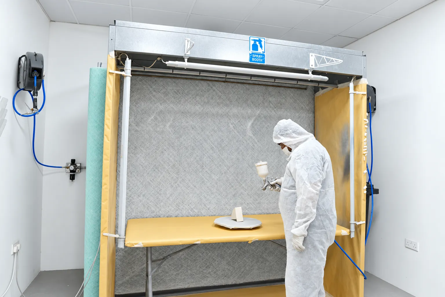
Paradigm 3D technician preparing the surface of printed parts before painting

Finished to your drawing,not just printed.

Layer lines are part of the as-printed surface. We remove supports, then finish the faces that matter for fit, look and assembly.

  • Support removal and cleaning planned with the build orientation.
  • Sanding and priming for visible faces and paint preparation.
  • Painting to your colour standard or a reference sample.
  • Threaded inserts and assembly of sub-components before delivery.
  • Dimensional checks on the critical features you identify.

FDM questionsengineers ask us.

Anything else? See all FAQs

Can FDM make functional end-use parts?

Yes. With the right material and build orientation, FDM parts work as tooling, housings and end-use components. Share the loads, temperatures and interfaces and we recommend a material.

Will the part have a smooth surface?

Layer lines are normally visible as printed. Orientation, layer thickness and finishing decide the final appearance, and we can sand and paint to a reference sample.

Can my part use the full 914 mm envelope?

The envelope is a machine specification, not a guaranteed part size. Orientation, supports and build setup reduce the usable space, so we tell you the largest single piece your geometry allows.

What tolerance can FDM hold?

Stratasys rates the F900 at ±0.089 mm or ±0.0015 mm/mm, whichever is greater. Achieved tolerance depends on geometry, material and orientation, so we state what is realistic for your part in the quote.

Can you print ULTEM 9085 cabin parts?

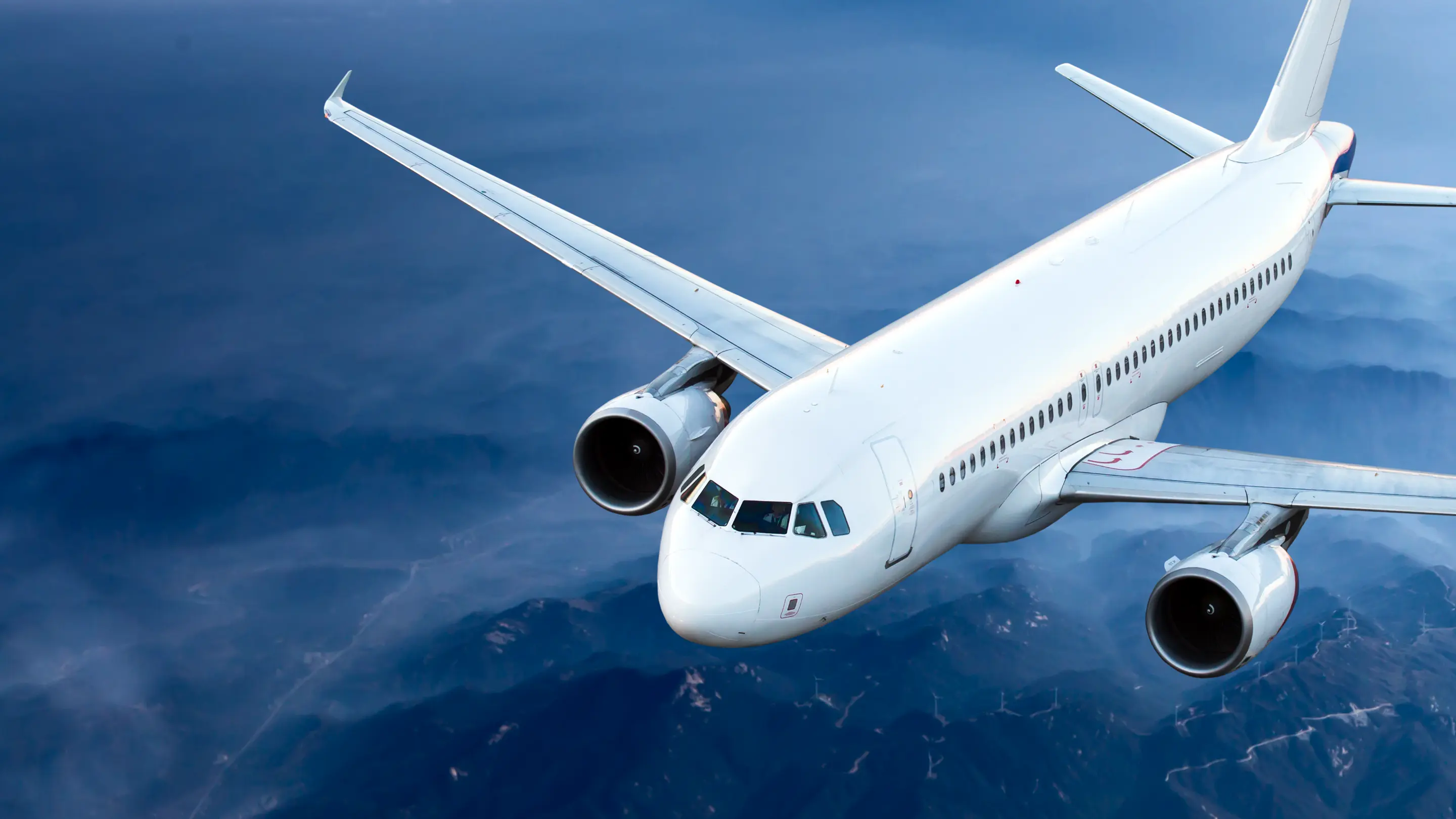
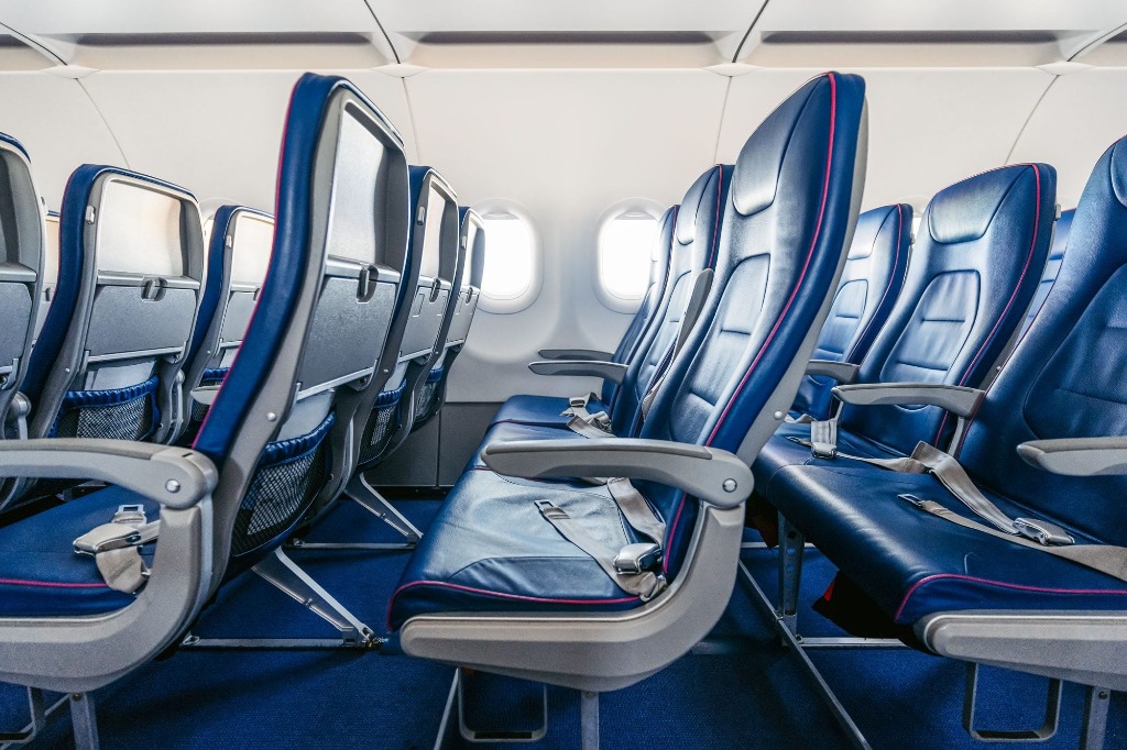
Yes. Paradigm 3D manufactures eligible aviation parts under a production arrangement with The Aviation AM Centre, the EASA Part 21G approval holder, which issues EASA Form 1 for parts supplied through that approved route. Aviation cabin parts

Which files do you need?

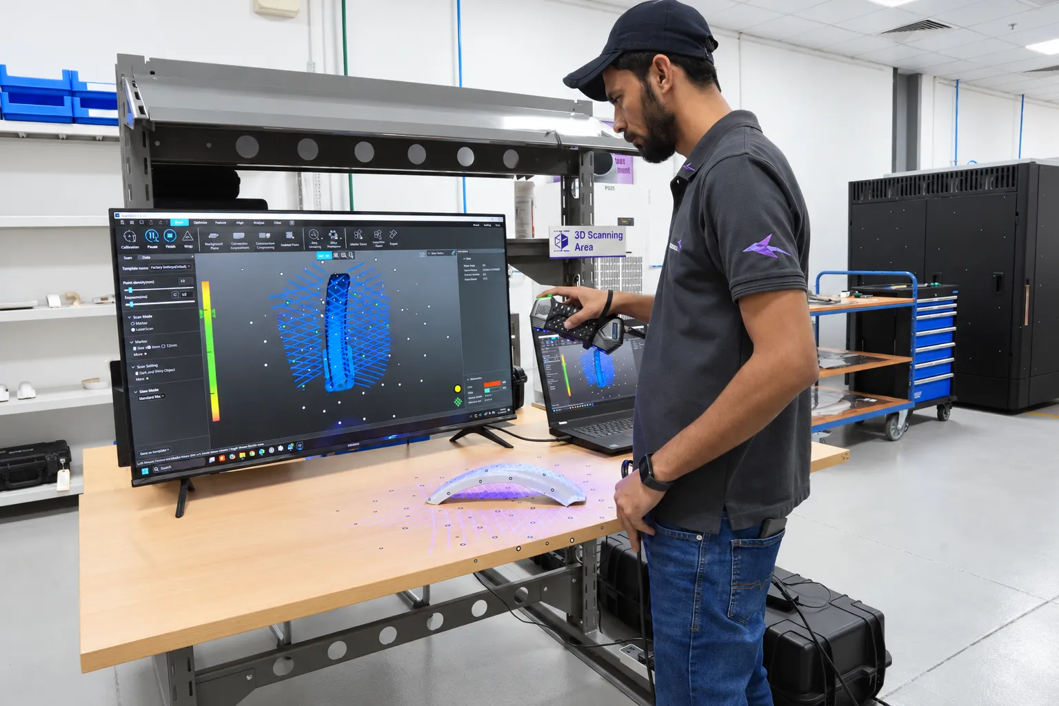
STEP or STL for 3D data and a PDF drawing for critical dimensions. If you only have the old part or photos, we can scan and model it.

Bring us the part.

Send a drawing, a CAD file, or photographs and the old part. Tell us what it does, how many you need and when.

Tell us what you need

Fields marked * are required. A drawing helps, but photos and a description are enough to start.

Your contact details
Your part
Add more detail (optional)
Drawings, CAD or photos (optional)

    Your files are used only to assess your part and are kept confidential. See our privacy policy.